

I was working on my 2002 Maxima BOSE radio with internal 6CD changer, in an attempt to see if I can add an AUX input for my iPhone/iPod. Along the way, I removed the radio from the car, and started to trace down the main printed circuit board to find where the audio input were for the CD, TAPE and AM/FM. I found that there are several place marked AUX IN, unfortunately, the components associated with this port were not installed, so I think that I can not just add a wire to these holes and expect to be able to drive the iPod/iPhone audio signal to go though the radio selector, so I have to do it another way.
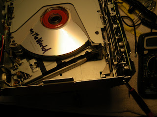
In doing these tracing, one of the CD already in the unit (there were 4) slid out unexpectedly, and I didn't think it was a problem. Wrong! When I hook the radio back up to the car, the CD changer made an attempt to play the CD that was in slot that no longer had a CD (the one that fell out) and I immediately got a "CD ERROR FO" (that's a zero) code on the radio display. I googled, and everyone said that I am toast and that I need to have it fixed or replaced, to the tuned of $300-2000. I took the radio back out, and opened the cover over the CD changer unit. I found the problem: The moving laser head that reads the CD is jammed hard against the multi-disk separator and cannot be moved out of the way. In the picture you see that one of the separator is angled downward and is sandwiched by the laser read head arm and disk top clamp. I carefully uncouple the head unit from the separator, making sure that I do not bend anything to prevent misalignment. The photos in this blog shows the various stage of jammed to free state. Along the way, I lost one of the pins that holds the multi-disk separators, and I fashioned a replacement using a small screw almost the same length. I filed the threads off to make it slide freely like the other one.
I also carefully removed the remaining CDs that are still inside the unit, and the entire multi-disk tray then dropped down to their lowest levels. I put everything back together, and back into the car. My CD ERROR FO is now gone!
More story later when I attempt to hook up the PA11-NIS iPod adapter. Its on order. Everyone says it will not work for a Maxima with integrated 6CD changer. We'll see.


